AIデータセンターの800Vラック保護:ホットスワップとDC遮断器の境界
800Vの電力経路で見るべき数字は、電圧そのものより「どこで、何を、どれだけ速く切り離せるか」だ。Google Search Consoleでは当サイトの800V電力記事に検索表示が続く一方、今回の上位クエリに保護回路の直接語はない。そこで、既存のAI電力ボトルネック整理と800V・GaN・SiCの比較から一段だけ進み、2026年9月時点の公開設計例で保護の境界を確認する。
800Vバスへ移すと、保護を一つの「遮断器」で代表させにくくなる。トレイ挿入時の突入電流を制御するホットスワップ、配電枝の短絡を切り離す回路、設備側の絶縁・接地・作業安全は、故障点と責任範囲が違うからだ。
TIの2026年3月の設計例は2線±400Vまたは800V、出力容量100µF、17kWの熱設計電力、25Aの過電流保護を前提にした回路例である。これは一般的なラック仕様ではない。自社の動作点と保護協調を検討するための単一リファレンス設計として読むべきだ。
| 保護レイヤー | 主な対象 | 公開例で確認できること | これだけでは分からないこと |
|---|
| トレイ/モジュール | 挿入時の突入、低電圧・過電圧、過電流、短絡 | TIは浮動基準のホットスワップ回路と制御例を示す | 別のラック、ケーブル、温度条件での適合性 |
| 配電枝 | ラック間・電源枝間の故障選択性 | InfineonとSolarEdgeは800VDC向けSSCB開発協業を発表 | 協業発表だけでは量産品、認証、実設備の遮断能力は確定しない |
| 施設・作業 | 接地方式、絶縁、アーク、保守・規格適合 | OCP資料は複数の接地・極構成を比較し、ULは標準の差分検討を進める | 全地域・全構成に共通する完成済み規格とは言えない |
要点は、トレイのホットスワップが配電系統全体のDC遮断器を代替するわけではないことだ。逆に、上流のSSCBだけでも、着脱時の容量充電や負荷の電圧条件は片付かない。
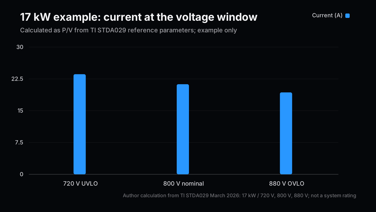
ここで役立つのは、データシートの一つの電流値より、入力電圧の幅で同じ電力を割り戻すことだ。TIの表では低電圧ロックアウトを720V、高電圧ロックアウトを880V、代表バスを800Vとしている。17kWを一定負荷とみなす単純計算は次の通り。
| 電圧 | 計算 | 電流 |
|---|
| 720V | 17,000W ÷ 720V | 23.61A |
| 800V | 17,000W ÷ 800V | 21.25A |
| 880V | 17,000W ÷ 880V | 19.32A |
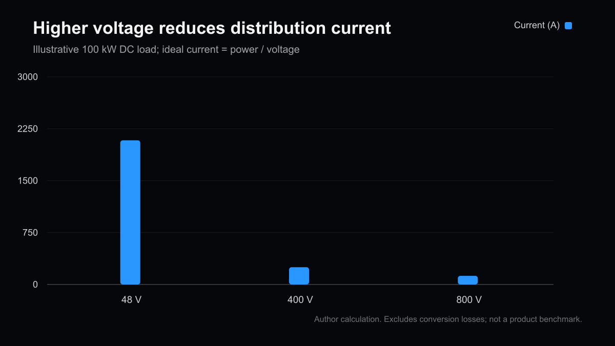
この計算はP/Vであり、過渡応答や変換効率を含まない。TIが低電圧側の23.6Aから余裕を見て25Aの電流制限値を置く理由を読み解く手掛かりにはなるが、その設定を別の設計へ転用する根拠にはならない。図はこの同じ計算を可視化したもので、実測性能ではない。
容量側も無視できない。コンデンサーの蓄積エネルギーは
E = 1/2 × C × V²
。TI例の100µFを800Vまで充電すると、
0.5 × 100×10⁻⁶ F × 800² V² = 32 J
となる。720Vでは25.92J、880Vでは38.72Jだ。電圧が1.1倍ならエネルギーは1.21倍になる。これは筆者の式への代入計算で、火災・アークの規模や放電時間を直接推定する値ではない。
TIのリファレンス回路は突入時に低い電流を保ちながら100µFを充電する試験、起動時短絡、緩やかな過電流、定常時短絡を分けて示す。論文内の設定例では、INA238の22Aアラートで制御を止める経路があり、急峻な短絡時は数µsでFETを切ると記載される。これらは当該評価回路の結果であり、別のバス配線やヒューズ・接触器との選択遮断を証明しない。
DCには交流のような自然な電流ゼロ点がないため、遮断方式やアーク管理を交流設備から単純に外挿できない。Infineonは2026年9月9日、SolarEdgeと800VDC配電向けSSCBの協業を拡大し、InfineonのSiC JFETを使う計画を発表した。会社発表はSSCBがマイクロ秒単位で故障を遮断する設計意図を説明するが、両社の開発発表を既に商用化・認証済みの製品として扱ってはいけない。
OCPの2026年3月LVDC白書は、700V/800V級であり得る複数の系統を比較する。例えば、350/700Vの双極TN-Sでは対地電圧を下げられる構成があり、700V単極TN-Sでは保護すべき活線極が一つという利点と、双極構成より大きいクリアランス要求が記される。どちらを選ぶかは入力電圧ラベルだけで決まらない。接地方式、故障電流経路、絶縁、コネクター、機器の耐圧、保守手順を一緒に決める必要がある。
比較時は、少なくとも次の問いを別々に置きたい。
- 突入:バス電圧・出力容量・投入順序に対し、FETの安全動作領域(SOA)を起動中も満たすか。
- 故障検出:高速短絡と緩慢な過負荷を同じ検出経路に頼らず、検出からゲート遮断までの遅延をどの試験で確認したか。
- 協調:枝故障を枝だけで切れるか。上流SSCB・ヒューズ・分岐保護のどれが先に動くかを波形と条件付きで示せるか。
- 残留電荷:遮断後の出力容量をどこへ、何秒で放電するか。TI例はIEC 62368-1の要件に合わせ、100µFを2秒未満で放電する回路を説明している。
- 物理実装:コネクターの接触順序、沿面・空間距離、温度上昇、センサー故障時の状態を構成ごとに確認したか。
UL SolutionsとOCPの協業は、800Vから最大1,500VDCを視野に、スイッチギア、盤、バスバー、ケーブル、過電流保護など既存基準のギャップを洗い出す段階だと説明される。この活動自体が、規格・検査・地域の法令解釈が完成済みとまでは言えないことを示す。Eatonも800VDCアーキテクチャを個別機器の置き換えではなく、電力・IT・冷却を共同設計する課題として説明している。
Protecting 800V AI Racks: Hot-Swap and DC Breaker Boundaries
The useful question about an 800 V power path is not simply how high the voltage goes. It is where a fault can be isolated, what equipment is inside that protection boundary, and what evidence supports the claimed response. Search Console still shows impressions for this blog’s AI-power coverage, but the latest top-query table contains no direct hot-swap or 800 V protection term. This article extends the existing AI power bottleneck overview and 800 V, GaN, and SiC comparison by examining public design material available as of September 2026.
An 800 V bus makes it harder to use the word “breaker” as if it described one device and one job. A tray hot-swap circuit manages the inrush when a module is connected. Distribution protection isolates faults between power branches. Facility engineering covers grounding, insulation, arc hazards, maintenance, and compliance. Their fault locations and owners differ.
Texas Instruments’ March 2026 reference design is built around a two-wire ±400 V or 800 V input, 100 µF output capacitance, 17 kW thermal design power, and a 25 A overcurrent limit. Those are assumptions in one worked example, not a universal rack specification. The paper is useful as a reproducible circuit case, not as proof that the same settings fit another rack, connector, or thermal envelope.
| Protection layer | Main concern | What the public example supports | What remains unproven |
|---|
| Tray or module | Inrush, undervoltage, overvoltage, overload, and short circuit | TI documents a floating-reference hot-swap design and test cases | Suitability across other bus, cable, and temperature conditions |
| Distribution branch | Selective fault isolation across rack and power branches | Infineon and SolarEdge announced an 800 VDC solid-state breaker development collaboration | Commercial availability, certification, and installation-level interrupt capability |
| Facility and workers | Grounding, insulation, arcing, maintenance, and codes | OCP compares multiple pole/grounding arrangements; UL is working on standards gaps | A single completed rule set applicable to all jurisdictions and topologies |
The important boundary is that a tray hot-swap controller does not replace an upstream DC breaker. The reverse is also true: a solid-state circuit breaker (SSCB) on a feeder does not by itself manage capacitor charging or safe module insertion.
A voltage window is more informative than a single headline current. TI’s example sets undervoltage lockout at 720 V, overvoltage lockout at 880 V, and uses 800 V as its nominal bus. Dividing 17 kW by each voltage gives a simple constant-power comparison:
| Voltage | Calculation | Current |
|---|
| 720 V | 17,000 W ÷ 720 V | 23.61 A |
| 800 V | 17,000 W ÷ 800 V | 21.25 A |
| 880 V | 17,000 W ÷ 880 V | 19.32 A |
This is only
I = P/V
. It excludes transient behavior and conversion losses. It helps explain why the worked example uses a 25 A current limit after calculating 23.6 A at the low-voltage boundary, but it does not make 25 A a transferable design recommendation. The accompanying figure plots only this arithmetic; it is not a measured performance curve.
Stored energy is another useful check. A capacitor stores
E = 1/2 × C × V²
. At 100 µF and 800 V, the calculation is
0.5 × 100×10⁻⁶ F × 800² V² = 32 J
. The same capacitance stores 25.92 J at 720 V and 38.72 J at 880 V. A 10% voltage increase produces a 21% increase in stored energy. This is the author’s calculation from the equation, not an estimate of fire or arc severity and not a discharge-time result.
TI separates startup inrush, startup into a short, gradual overload, and a steady-state output short in its lab results. The reference design uses a 22 A INA238 alert to disable the hot-swap path for gradual overload. It reports FET disable within 10 µs for that test, and within a few microseconds for a fast-rising short. These are results from TI’s specific circuit and test conditions. They do not establish selective coordination with an unrelated feeder breaker, fuse, cable, or contactor.
Direct current has no natural current zero in each cycle, so the interruption and arc problem cannot be inferred from an AC breaker label. On September 9, 2026, Infineon announced an expanded collaboration with SolarEdge on an 800 VDC SSCB, with Infineon SiC JFET technology at the core of the planned protection device. The announcement describes a design goal of microsecond interruption. It is evidence of development activity, not evidence that a certified production product has shipped or has a specified field life.
The Open Compute Project’s March 2026 LVDC white paper compares multiple topologies that can support 700 V or 800 V devices. One 350/700 V bipolar TN-S arrangement can reduce voltage to earth relative to a unipolar arrangement. A 700 V unipolar TN-S arrangement has only one live pole to protect, but the paper notes that it requires larger clearances than the bipolar TN-S option. The choice is not determined by the “800 V” label alone. Grounding, fault return path, insulation, connector design, device ratings, and service procedures have to fit together.
A diligence review can separate at least five questions:
- Inrush: Does the switching device remain within its safe operating area (SOA) while charging the specified capacitance at the intended bus voltage and insertion sequence?
- Detection: Are fast shorts and slow overloads detected through appropriate paths, and what measured latency exists from detection to gate turn-off?
- Coordination: Can a branch fault be isolated locally? Which device trips first across the SSCB, fuse, and branch protection, under what tested fault waveform?
- Residual charge: Where does the output capacitance discharge after shutdown, and how long does it take? TI’s 100 µF example includes a path intended to meet an under-two-second discharge condition described with IEC 62368-1.
- Physical implementation: Have connector sequencing, creepage and clearance, thermal rise, and sensor-fault behavior been evaluated for the actual grounding and pole arrangement?
UL Solutions says its OCP codes-and-standards workstream is examining gaps across switchgear, panelboards, busbars, cables, and overcurrent protection as data-center systems move toward roughly 800 VDC and potentially 1,500 VDC. That ongoing work is a signal that certification and local inspection practices are still part of the deployment path. Eaton’s 800 VDC paper likewise frames the problem as co-design across power, IT, and cooling instead of a drop-in replacement of one component.
The disciplined way to assess 800 VDC is to track which boundary has been specified, tested, and qualified rather than treating the voltage transition as a single adoption forecast. OCP’s August 2026 update describes both a side power rack that converts existing 480 VAC to ±400 V or 0–800 VDC near compute racks and a longer-term route that converts medium-voltage AC directly to 800 VDC for the data hall. Those paths may differ in facility work, protection points, and supplier qualification sequence.
| Scenario | What public sources say | Evidence to check next | Possible delay or disproof |
|---|
| Phased retrofit | OCP presents a sidecar route for existing facilities | ±400 V/800 V interface specs, interoperability tests, and field certifications | Building, connector, or service-procedure incompatibility |
| Direct 800 VDC | OCP describes a future medium-voltage AC to data-hall route | SST/transformer-rectifier coordination, redundancy, and maintainability | Utility/facility approvals, standardization, limited field evidence |
| Protection-component competition | TI has a hot-swap reference design; Infineon/SolarEdge announced SSCB development | Commercial ratings, certification, fault waveforms, temperature and lifetime data | Time from announcement to volume, heat/cost trade-offs, selectivity challenges |
These scenarios are an analytical framework, not adoption probabilities or revenue forecasts. Vendor statements should remain tied to their test setup; they do not establish customer deployments or market share.
The word “validated” should also be unpacked. TI reports separate tests for startup, startup into a short, gradual overcurrent, and a steady-state short. A useful diligence table would map each result to bus voltage, output capacitance, temperature, fault-injection point, measured interruption waveform, and the state of the circuit after clearing. That prevents a component datasheet rating from being mistaken for a system test of a particular topology.
Normal-operation efficiency and fault selectivity are separate axes. An SSCB can target fast response, yet its conduction loss, cooling burden, cost, nuisance-trip behavior, and coordination with redundant feeds still affect system value. Comparing it with a mechanical device on interruption speed alone misses the more practical question: under which current range and fault location can it isolate one branch without tripping the upstream path? If a public announcement does not disclose those conditions, they should remain unknown in the investment case.
There is also a deployment-sequence question. A sidecar retrofit can concentrate conversion and protection outside the IT rack, while direct facility distribution places more of the qualification burden upstream. Neither layout eliminates maintenance access, safe isolation, or commissioning tests; it relocates them. Public ecosystem specifications can show which interfaces are being standardized, but they cannot establish that every operator, installer, and local authority has adopted the same procedure. Evidence of interoperability across suppliers will matter as much as a component’s standalone benchmark.
The related AI power bottleneck article covers supply and conversion constraints, while the 800 V and GaN/SiC comparison focuses on semiconductor roles. This article adds a diligence checklist for insertion, short-circuit response, selective isolation, and worker safety between those layers.
- TI, Floating Ground Hot-Swap Architecture for 800V or ±400V DC Power Distribution (March 2026)
- Open Compute Project, Data Center Facility Power Distribution LVDC White Paper v1.0 (March 2026)
- Open Compute Project, 800VDC industry transition and SST specification update (August 2026)
- Infineon, SolarEdge collaboration on 800VDC solid-state protection (September 9, 2026)
- UL Solutions and OCP, safety and standards work for AI data centers
- Eaton, Deploying 800VDC Architectures for Large-Amperage Data Centers
Next Issue Ideas
- Assessing redundancy in 800 V power sidecars — Separate OCP sidecar topologies into A/B feeds and service domains, then trace the fault boundaries visible in public specifications.
- Qualification evidence for DC breakers — Compare SSCB and mechanical-device test conditions by voltage, current, selectivity, and lifetime instead of headline interruption speed.
- Certification gates for data-center power — Follow UL/OCP standards work and distinguish component qualification from facility operating approval.
This article is not investment advice. The author may hold securities of companies discussed. Generative AI assisted its preparation. Review the disclaimer before making investment decisions.