MangoBoostのDPUは何をオフロードするか:RoCEとNVMeの境界を検証
「MangoBoost DPUがCPUを解放してGPUを速くする」と読むと、ネットワークとストレージのどちらで待ち時間が減るのかが曖昧になる。私が今回確かめたかったのは、製品の宣伝文句を実際のデータ経路へ戻せるかという点だ。2026年9月25日時点の製品ページとSDKを照合し、経路ごとに確認する。
| 要点 | 読者が確認できること |
|---|
| 製品の境界 | BoostX RoCE AI、NRT、Baseは同じFPGA基盤の異なるカード |
| オフロードの境界 | RoCE AIはGPU間通信、NRTはNVMe/RDMA target。MLPerfの推論値からDPUの効果は単独では分からない |
| 計算の境界 | 400Gb/sは64GiB転送の理論下限を約1.37秒にするが、実効性能を保証しない |
以前のAI半導体スタートアップ比較ではDPUを「計算の外側」と分類した。本稿はその内側を、公開資料で再現できる範囲まで細分化する。MangoBoostを推論の中立レイヤーとして論じた記事の投資仮説も、まず何をオフロードする製品なのかを確定してから読みたい。
現行のBoostX製品概要は、RoCE AI、NRT、Baseを同一のFPGA基盤を共有する別カードとして列挙する。RoCE AIはAIクラスタのRDMA通信、NRTはNVMe/RoCEv2 target、Baseはカスタムdataplane用だ。製品資料の「最大400GbE」は共通基盤のネットワークインターフェース上限であり、NRTの表示は200GbE。全製品で400Gb/sの実効速度が出るという意味ではない。
ここを分けると、CPUオフロードという言葉の主語がはっきりする。
| 経路 | 公開資料で確認できる機能 | CPU/GPUについて言えること | まだ確認できないこと |
|---|
| GPU ↔ RoCE AI ↔ GPU | FPGAベースのRoCEv2、2×200GbE、GPUメモリへのP2P RDMA | ホストメモリを中継しない経路を構成できる | 個別ワークロードで節約したCPU時間、学習完了時間 |
| NVMe ↔ NRT ↔ ネットワーク | NVMe-oF RDMA target、namespaceとlistenerの制御 | I/O dataplaneをカード側に置ける | GPUまでの端から端の速度とCPU削減量 |
| 管理クライアント ↔ OPI bridge | storage APIのgRPC制御面 | 作成・設定とI/O経路を分けられる | networking/security APIの提供時期 |
| LLMBoost ↔ MI300X | MLPerf Inference v5.0への提出 | 推論ソフトを含むシステム結果が存在する | その結果の何割がDPUに由来するか |
RoCE AIのSDK概要は2×200GbEとPCIe Gen5 x8を2本、GPU P2P対応を明記する。NRTの手動設定資料はtarget transportをRDMAに限定し、subsystemごとのI/O queueのデフォルトを32とする。これらは異なる用途の仕様であり、数字を一つの「DPU速度」として合算できない。
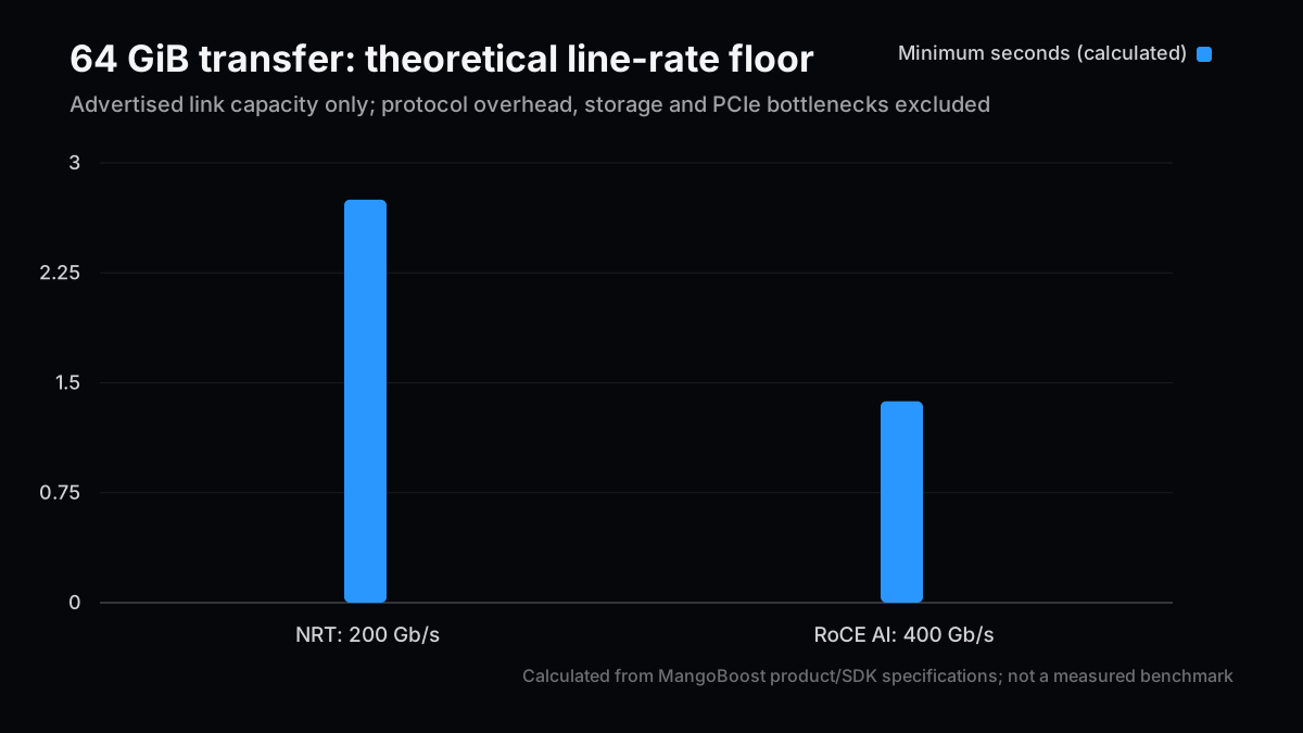
帯域の最大値を記事で使うなら、同じ単位に戻してから議論したい。64GiBのデータを、プロトコル overheadも混雑もゼロという仮定で移す場合の下限を計算する。これは私の計算で、MangoBoostの実測値ではない。
gib = 64
bytes_to_move = gib * 1024**3
for link_gbps in (200, 400):
    seconds = bytes_to_move * 8 / (link_gbps * 1_000_000_000)
    print(f"{link_gbps} Gb/s: {seconds:.3f} s minimum")
結果は200Gb/sで約2.749秒、400Gb/sで約1.374秒。帯域を2倍にすると、この単純な転送下限は半分になる。一方、実際の転送にはEthernet/RDMA overhead、PCIe、SSDやGPUメモリ、packet loss、輻輳制御が入る。複数ノードのジョブ全体には演算と同期もあるため、ジョブ時間が半分になるという推論は成り立たない。
また、GPU統合のSDK説明は重要な留保を付けている。同ページに載る実験結果の多くは旧RNICプラットフォームで得られ、BoostX RoCE AIの測定値へ今後更新予定だという。掲載の帯域グラフを現行カードの確定性能として引用しない。
SDKが示すP2P経路には前提がある。GPUとRoCE AIカードを同じPCIe switchの下に置き、ドライバーとGPU側のメモリ登録条件を満たす必要がある。SDKによれば、NVIDIA GPUでは
nvidia-peermem
が必要で、AMD GPUではROCmRDMAの経路を使う。ACSの設定もP2Pに影響するが、検証環境での変更は運用管理者が安全性と分離要件を確認して判断すべきだ。ここでは設定変更を実行したとは主張しない。
比較実験を組むなら、カードを入れた構成と対照構成でGPU、CPU、SSD、switch、ドライバー、モデル、batch size、payload、並列数を揃える。最低限、次を同時に記録する。
- RDMA P2Pが成立したか。
perftest
のGPU bufferテストとNCCL/RCCLログで経路を確認する。 - 同じpayloadでthroughput、p50/p99 latency、CPU core-secondsを測る。
- storage workloadならNRT targetのI/O queue、SSD台数、namespace、listenerを記録する。
- 最後に学習または推論ジョブの完了時間とGPU idle比率を比較する。
この順序なら「NICの公称帯域」と「GPUジョブの改善」を飛躍なく接続できる。CPU使用率だけが下がりジョブ時間が変わらない場合も、DPUの役割はCPU余力や分離にあるかもしれない。逆にジョブが速くなっても、ストレージ・ネットワーク・推論ソフトのどの変更が効いたかは、単一要因の対照試験がなければ不確実だ。
MLCommonsのInference v5.0結果にはMangoBoostのMI300X/LLMBoost提出がある。これは提出条件下のシステム結果を確認する一次資料だ。しかし提出名はDPUを単独で比較したA/B試験ではない。「MLPerfの値=BoostXが生んだ改善」とは読めない。GPU数、モデル、scenario、software stackをそろえない他社行との単純な倍率比較も避ける。
もう一つは「セキュリティも今すべてオフロード済み」という読み違い。MangoBoostのOPI bridge資料は、OPI APIで現在カバーするのはstorageで、networkingとsecurityはplannedと記す。この記述はOPIの公開API範囲についてであり、会社全体の製品機能が存在しないことまで証明しない。確認できた範囲をそこで止める。
現時点で最も堅い結論は、BoostXがFPGA基盤の実際のハードウェアカードで、RoCE通信とNVMe targetの異なる経路を扱うことだ。CPU削減、GPU稼働率、費用対効果は、ワークロードと対照群を定義して初めて比較できる。製品説明から投資判断までの間には、測定の一段が残っている。
なお、同じFPGA基盤でもファームウェア、PCIe配置、SSD構成、software stackが変われば結果は変わる。評価表には製品名だけでなくカード型番と測定環境を残したい。これを省くと、後から別の構成で再測定しても改善の原因を追えない。
次号の記事案
- RoCEの輻輳制御を検証する — 同じpayloadとfan-inでp99 latencyを測り、packet sprayingの効果と限界を切り分ける。
- NVMe-oF targetのqueue budgetを設計する — subsystem、queue、SSD台数を固定した再現可能な負荷試験を組む。
- GPU idle時間の測定表を作る — DPU導入前後でnetwork、storage、compute待ちを別々に記録する。
本稿は情報提供を目的とし、特定銘柄の売買を推奨しません。生成AIの支援を受けて作成し、公開一次資料を確認しました。詳細は免責事項をご覧ください。
What Does MangoBoost’s DPU Offload? Testing the RoCE and NVMe Boundaries
“MangoBoost frees the CPU and makes the GPU faster” skips a crucial question: which data path actually changes? I wanted to map that claim back to hardware and software interfaces. This article checks the product catalog and SDK as available on September 25, 2026, then separates documented capabilities from performance that still needs a controlled test.
| Takeaway | What the evidence supports |
|---|
| Product boundary | BoostX RoCE AI, NRT and Base are distinct cards on a shared FPGA foundation |
| Offload boundary | RoCE AI handles RDMA networking; NRT is an NVMe/RDMA target. An MLPerf inference submission does not isolate the DPU |
| Calculation boundary | At 400Gb/s, the ideal transfer floor for 64GiB is about 1.37 seconds, not a measured application result |
My earlier AI semiconductor startup map placed the DPU outside the compute core. Here I break that category into actual data paths. The earlier MangoBoost investment thesis also deserves to be read against the current hardware catalog before attributing utilization gains.
The current BoostX platform page lists three cards on a common FPGA foundation. RoCE AI targets RDMA traffic across AI clusters. NRT acts as an NVMe/RoCEv2 target. Base supplies a programmable dataplane for custom IP. “Up to 400GbE” describes the platform interface; the NRT product is labeled 200GbE. It would be wrong to read the former as a measured throughput promise for every card.
That separation gives the phrase “CPU offload” a concrete subject.
A dataplane offload also has a control plane. A host or management service still decides which storage namespace to expose, where traffic should be sent and how failures should be handled. The point is to move the repeated per-packet or per-I/O work onto an accelerator after policy has been installed. That makes the design attractive when a large number of similar operations would otherwise consume host cores. It says much less about a single small inference request, where scheduling, model execution or memory capacity could dominate. The comparison therefore starts by identifying the operation that the host used to perform, not by naming the accelerator that now appears in the rack.
| Path | Documented function | What we can say about CPU or GPU | What remains unmeasured |
|---|
| GPU ↔ RoCE AI ↔ GPU | FPGA-based RoCEv2, 2×200GbE, GPU-memory P2P RDMA | A path can bypass the host-memory staging buffer | CPU time saved and full training-job duration |
| NVMe ↔ NRT ↔ network | NVMe-oF RDMA target with namespaces and listeners | The I/O dataplane can live on the card | End-to-end transfer to a GPU and CPU reduction |
| Management client ↔ OPI bridge | gRPC control plane for storage APIs | Configuration is separate from the I/O path | Delivery dates for networking and security APIs |
| LLMBoost ↔ MI300X | MLPerf Inference v5.0 submission | A system result including inference software exists | The DPU's independent contribution |
The RoCE AI SDK overview specifies 2×200GbE, two PCIe Gen5 x8 host interfaces and GPU P2P support. The NRT configuration guide specifies RDMA as the supported target transport and 32 as the default maximum I/O queues per subsystem. These are different workloads and cannot be added into one “DPU speed.”
The hardware description also corrects an easy mistake in older commentary: MangoBoost should not be described as a purely chipless software layer. The published BoostX lineup consists of physical, FPGA-based cards, while LLMBoost is a separate inference-software thread. A company can sell both, but a result from the software thread does not automatically validate the networking card, and a networking feature does not prove a serving-stack improvement. For procurement or diligence, I would ask for the exact bill of materials, firmware and software version, and whether the workload used RoCE AI, NRT, both, or neither. Without that inventory, even a repeatable benchmark may answer the wrong question.
A link claim becomes easier to interpret after putting bytes and bits on the same scale. Consider a 64GiB transfer with zero protocol overhead, contention or other bottlenecks. The following is my calculation, not a MangoBoost measurement.
gib = 64
bytes_to_move = gib * 1024**3
for link_gbps in (200, 400):
    seconds = bytes_to_move * 8 / (link_gbps * 1_000_000_000)
    print(f"{link_gbps} Gb/s: {seconds:.3f} s minimum")
The ideal floor is about 2.749 seconds at 200Gb/s and 1.374 seconds at 400Gb/s. Doubling link capacity halves this transfer-only floor. Ethernet/RDMA overhead, PCIe topology, SSD and GPU-memory bandwidth, loss and congestion all raise real transfer time. Compute and synchronization add to a full job, so a twofold application speedup does not follow.
The bound can also be used in reverse. If a 64GiB transfer takes ten seconds on an otherwise isolated 400Gb/s link, its measured payload rate is about 55Gb/s: 64 × 2^30 × 8 ÷ 10 ÷ 10^9. That is an observation to diagnose, not proof that the card is defective. Small I/O sizes, limited queue depth, a slower SSD, PCIe placement or software copies could each explain the gap. Conversely, a reported 400Gb/s aggregate network rate does not mean one flow, one GPU or one storage target reaches that rate. The unit, aggregation level and topology must accompany every number.
The GPU integration guide contains a particularly useful caveat: many of its experimental results were collected on a legacy RNIC platform, and the page says BoostX RoCE AI measurements will replace them in a later revision. Those figures should not be presented as definitive measurements of the current card.
P2P has prerequisites. The SDK calls for the GPU and RoCE AI card to sit under the same PCIe switch, with working drivers and GPU memory registration. It notes
nvidia-peermem
for NVIDIA GPUs and a ROCmRDMA path for AMD GPUs. ACS settings also affect P2P; an operator should assess security and isolation requirements before changing them. I have not run or changed a production cluster for this article.
The same PCIe-switch requirement is particularly useful because it can turn an apparently successful benchmark into the wrong experiment. A test can run while its traffic traverses the CPU root complex rather than the intended peer-to-peer path. Logging only throughput would miss that distinction. A short capture of device topology, memory-registration success and the transport selected by the collective library should be part of the result. If a proposed test changes ACS or another isolation setting, document the platform's security tradeoff and obtain the operator's approval first. The article's checklist is a measurement design, not a claim that I executed it on MangoBoost hardware.
A useful comparison holds the GPU, CPU, SSD, switch, driver, model, batch size, payload and concurrency fixed between configurations. Record four layers together:
- Verify P2P with a GPU-buffer
perftest
run and NCCL or RCCL logs. - Measure throughput, p50/p99 latency and CPU core-seconds at the same payload.
- For storage, record NRT queue counts, SSD count, namespaces and listeners.
- Finally compare job completion time and the GPU idle fraction.
This connects the NIC's advertised bandwidth to the application without skipping steps.
For CPU accounting, a percentage alone is weak evidence. CPU utilization can fall because a job slowed down, completed fewer requests or moved work to another process. Core-seconds per fixed amount of useful output, paired with request throughput and latency, gives a more interpretable denominator. For the GPU, utilization counters should be paired with achieved tokens per second or training samples per second, since a device may look busy while spending time on inefficient kernels. Repeated runs and a stated variance matter too: a small gain that sits inside run-to-run noise is not a meaningful offload result. These are measurement choices, not vendor-specific performance claims.
Lower CPU use with unchanged job time may still be useful for capacity or isolation. Faster jobs, however, do not reveal whether the network, storage or inference software caused the gain unless a single-factor control is included.
The MLCommons Inference v5.0 results include a MangoBoost MI300X/LLMBoost submission. That is primary evidence of a submitted system result under the benchmark's conditions. It is not a DPU-on versus DPU-off experiment. Comparing its raw number with another vendor's different GPU count, model, scenario or software stack would not isolate MangoBoost's DPU either.
A second trap is treating every planned interface as shipped. MangoBoost's OPI bridge overview says the OPI API covers storage today, while networking and security are planned. That statement defines the public OPI API's scope; it does not establish the absence of every security feature elsewhere in the company.
The firm conclusion is narrower and more useful: BoostX is real FPGA-based card hardware with distinct RoCE networking and NVMe-target paths. CPU savings, GPU utilization and return on investment require a specified workload and matched controls. A product page is the start of the diligence, not its outcome.
This distinction matters for a buyer comparing a DPU with a conventional RDMA NIC or a software optimization. Choose one constrained workload first: for instance, a fixed distributed-training checkpoint path or a fixed NVMe-oF read pattern. Keep the traffic matrix and failure behavior visible. Ask separately whether the change frees host cores, improves tail latency, raises useful GPU work or simply shifts operational responsibility to the card's firmware and management layer. All four can be valuable, but their business value and integration costs differ. A deployment decision also needs supportability, upgrade and observability evidence that neither an advertised bandwidth figure nor an inference leaderboard can supply.
Next Issue Ideas
- Test RoCE congestion control — Compare p99 latency at matched payload and fan-in to isolate packet-spraying effects.
- Budget NVMe-oF target queues — Fix subsystem, queue and SSD counts in a reproducible load test.
- Build a GPU idle-time ledger — Record network, storage and compute stalls separately before and after a DPU change.
This article is informational and does not recommend trading any security. It was prepared with generative AI assistance and checked against public primary sources. See the disclaimer.