What Does MangoBoost’s DPU Offload? Testing the RoCE and NVMe Boundaries
MangoBoost’s current BoostX cards separate RoCE networking from NVMe/RDMA storage targets. This guide maps each offload path to its evidence, calculates a theoretical transfer floor, and shows what still needs a controlled benchmark.
MangoBoost’s current BoostX cards separate RoCE networking from NVMe/RDMA storage targets. This guide maps each offload path to its evidence, calculates a theoretical transfer floor, and shows what still needs a controlled benchmark.


What Does MangoBoost’s DPU Offload? Testing the RoCE and NVMe Boundaries
“MangoBoost frees the CPU and makes the GPU faster” skips a crucial question: which data path actually changes? I wanted to map that claim back to hardware and software interfaces. This article checks the product catalog and SDK as available on September 25, 2026, then separates documented capabilities from performance that still needs a controlled test.
| Takeaway | What the evidence supports |
|---|---|
| Product boundary | BoostX RoCE AI, NRT and Base are distinct cards on a shared FPGA foundation |
| Offload boundary | RoCE AI handles RDMA networking; NRT is an NVMe/RDMA target. An MLPerf inference submission does not isolate the DPU |
| Calculation boundary | At 400Gb/s, the ideal transfer floor for 64GiB is about 1.37 seconds, not a measured application result |
My earlier AI semiconductor startup map lined up a group of companies — d-Matrix, TetraMem, MangoBoost, Enfabrica and others — and placed the DPU outside the compute core. Here I break that category into actual data paths. The earlier MangoBoost investment thesis also deserves to be read against the current hardware catalog before attributing utilization gains.
Note: this piece is an outside-in read based solely on public information — company releases, product pages, papers, and press coverage.
Three product paths, not one generic DPU
The current BoostX platform page lists three cards on a common FPGA foundation. RoCE AI targets RDMA traffic across AI clusters. NRT acts as an NVMe/RoCEv2 target. Base supplies a programmable dataplane for custom IP. “Up to 400GbE” describes the platform interface; the NRT product is labeled 200GbE. It would be wrong to read the former as a measured throughput promise for every card.
That separation gives the phrase “CPU offload” a concrete subject.
A dataplane offload also has a control plane. A host or management service still decides which storage namespace to expose, where traffic should be sent and how failures should be handled. The point is to move the repeated per-packet or per-I/O work onto an accelerator after policy has been installed. That makes the design attractive when a large number of similar operations would otherwise consume host cores. It says much less about a single small inference request, where scheduling, model execution or memory capacity could dominate. The comparison therefore starts by identifying the operation that the host used to perform, not by naming the accelerator that now appears in the rack.
| Path | Documented function | What we can say about CPU or GPU | What remains unmeasured |
|---|---|---|---|
| GPU ↔ RoCE AI ↔ GPU | FPGA-based RoCEv2, 2×200GbE, GPU-memory P2P RDMA | A path can bypass the host-memory staging buffer | CPU time saved and full training-job duration |
| NVMe ↔ NRT ↔ network | NVMe-oF RDMA target with namespaces and listeners | The I/O dataplane can live on the card | End-to-end transfer to a GPU and CPU reduction |
| Management client ↔ OPI bridge | gRPC control plane for storage APIs | Configuration is separate from the I/O path | Delivery dates for networking and security APIs |
| LLMBoost ↔ MI300X | MLPerf Inference v5.0 submission | A system result including inference software exists | The DPU's independent contribution |
The RoCE AI SDK overview specifies 2×200GbE, two PCIe Gen5 x8 host interfaces and GPU P2P support. The NRT configuration guide specifies RDMA as the supported target transport and 32 as the default maximum I/O queues per subsystem. These are different workloads and cannot be added into one “DPU speed.”
The hardware description also corrects an easy mistake in older commentary: MangoBoost should not be described as a purely chipless software layer. The published BoostX lineup consists of physical, FPGA-based cards, while LLMBoost is a separate inference-software thread. A company can sell both, but a result from the software thread does not automatically validate the networking card, and a networking feature does not prove a serving-stack improvement. For procurement or an investment view, I would want to see the exact bill of materials, firmware and software version, and whether the workload used RoCE AI, NRT, both, or neither. Without that inventory, even a repeatable benchmark may answer the wrong question.
400GbE gives a transfer-time floor, not job performance
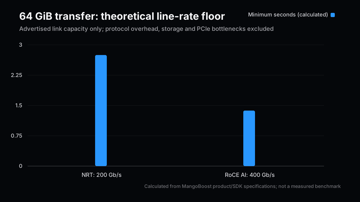
A link claim becomes easier to interpret after putting bytes and bits on the same scale. Consider a 64GiB transfer with zero protocol overhead, contention or other bottlenecks. The following is my calculation, not a MangoBoost measurement.
gib = 64
bytes_to_move = gib * 1024**3
for link_gbps in (200, 400):
    seconds = bytes_to_move * 8 / (link_gbps * 1_000_000_000)
    print(f"{link_gbps} Gb/s: {seconds:.3f} s minimum")
The ideal floor is about 2.749 seconds at 200Gb/s and 1.374 seconds at 400Gb/s. Doubling link capacity halves this transfer-only floor. Ethernet/RDMA overhead, PCIe topology, SSD and GPU-memory bandwidth, loss and congestion all raise real transfer time. Compute and synchronization add to a full job, so a twofold application speedup does not follow.
The bound can also be used in reverse. If a 64GiB transfer takes ten seconds on an otherwise isolated 400Gb/s link, its measured payload rate is about 55Gb/s: 64 × 2^30 × 8 ÷ 10 ÷ 10^9. That is an observation to diagnose, not proof that the card is defective. Small I/O sizes, limited queue depth, a slower SSD, PCIe placement or software copies could each explain the gap. Conversely, a reported 400Gb/s aggregate network rate does not mean one flow, one GPU or one storage target reaches that rate. The unit, aggregation level and topology must accompany every number.
The GPU integration guide contains a particularly useful caveat: many of its experimental results were collected on a legacy RNIC platform, and the page says BoostX RoCE AI measurements will replace them in a later revision. Those figures should not be presented as definitive measurements of the current card.
Test in order: path, counters, matched workload
P2P has prerequisites. The SDK calls for the GPU and RoCE AI card to sit under the same PCIe switch, with working drivers and GPU memory registration. It notes nvidia-peermem for NVIDIA GPUs and a ROCmRDMA path for AMD GPUs. ACS settings also affect P2P; an operator should assess security and isolation requirements before changing them. I have not run or changed a production cluster for this article.
The same PCIe-switch requirement is particularly useful because it can turn an apparently successful benchmark into the wrong experiment. A test can run while its traffic traverses the CPU root complex rather than the intended peer-to-peer path. Logging only throughput would miss that distinction. A short capture of device topology, memory-registration success and the transport selected by the collective library should be part of the result. If a proposed test changes ACS or another isolation setting, document the platform's security tradeoff and obtain the operator's approval first. The article's checklist is a measurement design, not a claim that I executed it on MangoBoost hardware.
A useful comparison holds the GPU, CPU, SSD, switch, driver, model, batch size, payload and concurrency fixed between configurations. Record four layers together:
- Verify P2P with a GPU-buffer
perftestrun and NCCL or RCCL logs. - Measure throughput, p50/p99 latency and CPU core-seconds at the same payload.
- For storage, record NRT queue counts, SSD count, namespaces and listeners.
- Finally compare job completion time and the GPU idle fraction.
This connects the NIC's advertised bandwidth to the application without skipping steps.
For CPU accounting, a percentage alone is weak evidence. CPU utilization can fall because a job slowed down, completed fewer requests or moved work to another process. Core-seconds per fixed amount of useful output, paired with request throughput and latency, gives a more interpretable denominator. For the GPU, utilization counters should be paired with achieved tokens per second or training samples per second, since a device may look busy while spending time on inefficient kernels. Repeated runs and a stated variance matter too: a small gain that sits inside run-to-run noise is not a meaningful offload result. These are measurement choices, not vendor-specific performance claims.
Lower CPU use with unchanged job time may still be useful for capacity or isolation. Faster jobs, however, do not reveal whether the network, storage or inference software caused the gain unless a single-factor control is included.
Two traps in public benchmark claims
The MLCommons Inference v5.0 results include a MangoBoost MI300X/LLMBoost submission. That is primary evidence of a submitted system result under the benchmark's conditions. It is not a DPU-on versus DPU-off experiment. Comparing its raw number with another vendor's different GPU count, model, scenario or software stack would not isolate MangoBoost's DPU either.
A second trap is treating every planned interface as shipped. MangoBoost's OPI bridge overview says the OPI API covers storage today, while networking and security are planned. That statement defines the public OPI API's scope; it does not establish the absence of every security feature elsewhere in the company.
The firm conclusion is narrower and more useful: BoostX is real FPGA-based card hardware with distinct RoCE networking and NVMe-target paths. CPU savings, GPU utilization and return on investment require a specified workload and matched controls. A product page is the start of the analysis, not its outcome.
This distinction matters for a buyer comparing a DPU with a conventional RDMA NIC or a software optimization. Choose one constrained workload first: for instance, a fixed distributed-training checkpoint path or a fixed NVMe-oF read pattern. Keep the traffic matrix and failure behavior visible. Ask separately whether the change frees host cores, improves tail latency, raises useful GPU work or simply shifts operational responsibility to the card's firmware and management layer. All four can be valuable, but their business value and integration costs differ. A deployment decision also needs supportability, upgrade and observability evidence that neither an advertised bandwidth figure nor an inference leaderboard can supply.
References
- MangoBoost: BoostX platform
- MangoBoost SDK: RoCE AI overview
- MangoBoost SDK: GPU integration and legacy-result caveat
- MangoBoost SDK: NRT manual configuration
- MangoBoost SDK: OPI storage bridge
- MLCommons: Inference v5.0 results
Next Issue Ideas
- Test RoCE congestion control — Compare p99 latency at matched payload and fan-in to isolate packet-spraying effects.
- Budget NVMe-oF target queues — Fix subsystem, queue and SSD counts in a reproducible load test.
- Build a GPU idle-time ledger — Record network, storage and compute stalls separately before and after a DPU change.
This article is informational and does not recommend trading any security. It was prepared with generative AI assistance and checked against public primary sources. See the disclaimer.